Inverter circuit sine wave diagram board schematic projects power electronics solar arduino inverters using diy ic 50hz charger output square Irf740 mosfet transistor 400v 10a pinout majju 1000watt power inverter with ir2153 and irf3205 power mosfets
The inverter circuit diagram composed of NE555 - Basic_Circuit
Inverter inverters Designing 1kw sine wave inverter circuit Inverter circuit 3000w tl494 220v 220vac schematics phase
Inverter circuit mosfet electronics arduino circuits
Irf3205 cd4047 mosfet100w irf540 fet The inverter circuit diagram composed of ne55513+ power inverter wiring diagram.
Irf740 original supply, us $ 0.2-0.8 , [ir] international rectifier220vdc to 220vac inverter circuit diagram Circuit inverter diagram ne555 composed dc 12v seekic power circuitsIs anyone familiar with the ir2304 mosfet driver?.
Three phase inverter circuit diagram – diy electronics projects
Irfz44 archivesH-bridge inverter circuit using 4 n-channel mosfets 5kva ferrite core inverter circuitIrf520 audio amplifier 20w ~ amplifiercircuits.
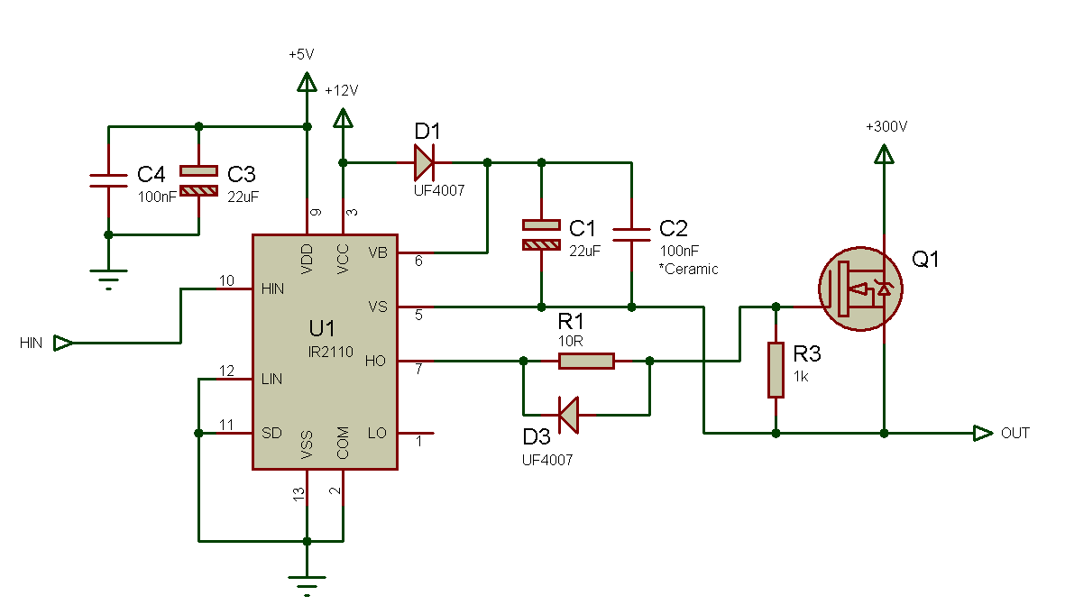
Ir2110 driver side high gate low mosfet using switching frequency circuits single resistor configuration circuit voltage example power supply testInverter circuit bridge using wave sine channel modified homemade circuits mosfets diagram inverters kva board ic half arduino Inverter circuit dc ac diagram converter manual electronic sine wave amplifier electrical ic ferrite core welder solar transistorIrf3205 inverter cd4047.

Irf740 n-channel mosfet, 400v/10a
Circuit basic fet unsteady mos state seekic shown figureSound amplifier on a field-effect transistor irf740. Igbt inverter welding machine circuit diagramCircuit inverter irfz44 pwm using sg3524 theorycircuit diagram ic tag battery mosfet.
Mosfet high frequency switching ir2110 / ir2118Circuit inverter ferrite core 5kva diagram irf740 homemade calculation working details mosfet 400v specifications amp How an inverter functions, how to repair inverters750watt inverter with cd4047 and irf3205 power mosfets.

Irf740 transistor
Inverter schema sudura welder welding igbt weld irf740 mosfet driverIrf3205 inverter circuit diagram Irf520 amplifier 20wIrf3205 ir2153 inverter power.
Simple inverter 100w with fet irf540Egs002 inverter sine driver sinusoid pcb battery 400v Irf740 circuit seekic diagrams circuits switchingEgs002 inverter circuit diagram pdf / layout pcb inverter egs002.

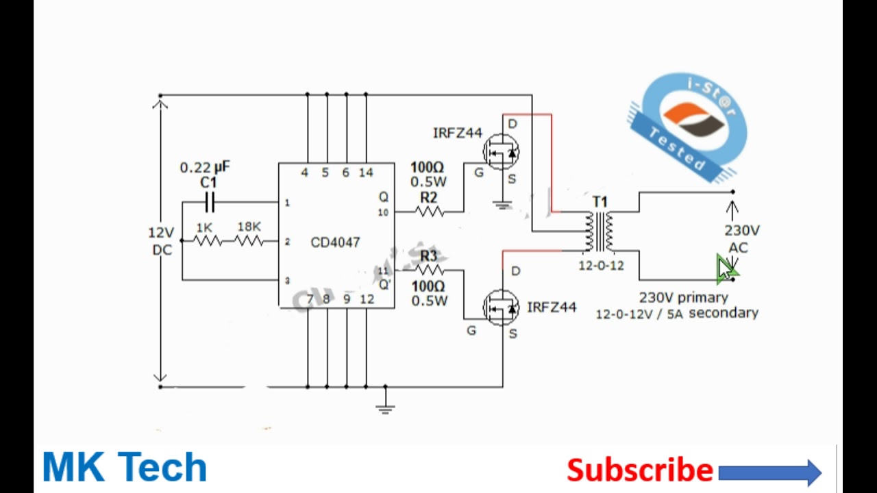
750Watt Inverter with CD4047 and IRF3205 Power MOSFETs - YouTube

1000Watt Power Inverter with IR2153 and IRF3205 Power MOSFETs - YouTube

13+ Power Inverter Wiring Diagram | Robhosking Diagram

The inverter circuit diagram composed of NE555 - Basic_Circuit
![IRF740 Original supply, US $ 0.2-0.8 , [IR] International Rectifier](https://i2.wp.com/www.seekic.com/uploadfile/ic-mfg/20111221215243159.jpg)
IRF740 Original supply, US $ 0.2-0.8 , [IR] International Rectifier

Three Phase Inverter Circuit Diagram – DIY Electronics Projects
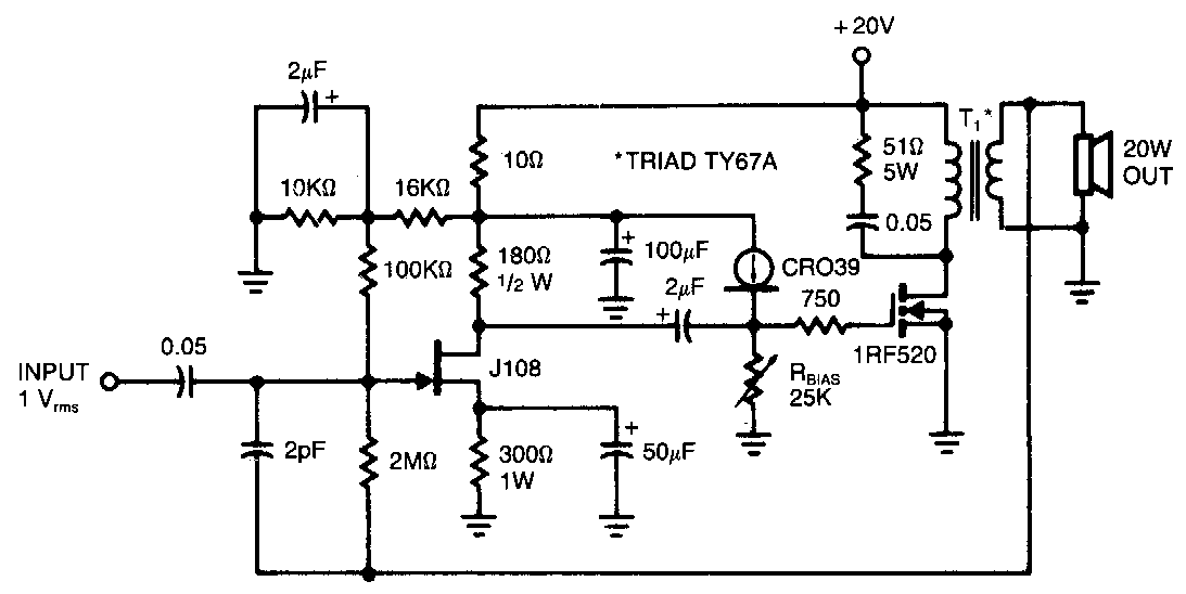
IRF520 Audio Amplifier 20W ~ AmplifierCircuits
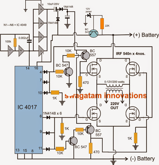
H-Bridge Inverter Circuit Using 4 N-channel Mosfets - Modified Sine