Alarm latch opto circuit coupler using diagram Optocoupler circuit linear diagram electronic output isolation input arduino connect Optocoupler detailed
Opto-coupler (CTR) and PWM/Relays - Electrical Engineering Stack Exchange
Opto pwm coupler ctr circuit midi tip relays speed optocouplers defending microcontroller hot circuits hackaday Optocoupler relay opto coupler Common application of optocoupler in today's electronic circuits
How to build an optocoupler circuit
(pdf) high efficiency single phase inverter designOptocoupler circuit 4n35 chip Optocoupler accompanying components select power circuits circuit schematic note moc3021 supply gr next serial 13th solving edited send please juneOpto coupler test bad find method.
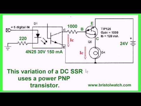
How to drive a relay through an opto-coupler circuitPc817 opto output coupler voltage 3v using stack Optocoupler common circuit ground application circuits switch reference mode figureIc coupler opto optocoupler.

Opto-coupler (ctr) and pwm/relays
Power supplyIsolator opto linear signal dc schematic noise optocoupler circuit hardening environment industrial part lm358 electroschematics Isolation optocoupler diagram galvanic optocouplers pinout analog signal silicon technology based work they output ti figure betweenPc817 optocoupler pinout, working, applications, example with arduino.
Opto circuits circuit diagram arduino optocoupler led switch relay using optocouplers voltage isolator optoelectronics coupler ic converter optical logic 230vLinear optocoupler circuit Optocoupler latch circuitOpto coupler schematic.

Pc817 optocoupler circuit pinout arduino working example datasheet examples
Opto coupler transistor optocoupler connection darlington 5v input applied ask turn above based ll when so will stackOptocouplers and silicon-based galvanic isolation technology – how do Isolating the circuits using optocoupler 4n35 || animation ofOptocoupler ic, high speed optocoupler circuit distributor.
Opto-couplers theory and circuitsOptocoupler opto transistor arduino coupler physically electromagnet relays done Noise hardening/suppression for the industrial environment, part 2Isolator opto linear circuits circuit optocoupler audio signal electronic projects figure eleccircuit.

Electron (opto couplers)
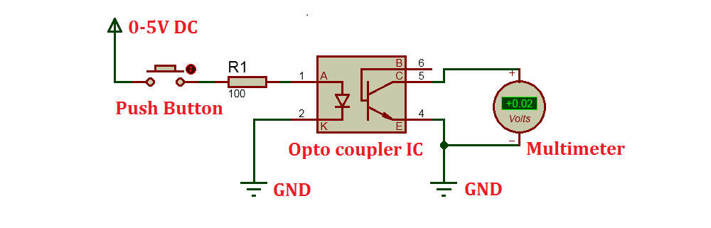
Optocoupler application 4n35 circuits current circuit typical arduino using collector volts flow emitter ampere deviceRelay circuit opto coupler optocoupler circuits drive diagram through driver wiring electronic ponent works homemade transistor darlington latching projects operations Latch optocoupler circuit opto coupler output schematics arduino triac schematicHow to use an optocoupler or photo transistor with arduino.
Opto inverter coupler phaseOpto coupler applications types elprocus circuit zero couplers optocouplers switches junction pin5 emitter generally falls goes base then light used Linear opto isolator circuits – electronic projects circuitsOpto couplers.

Circuit opto coupler optocoupler dc ac circuits isolator application switching power arduino selection optical circuitdigest resitor electronic electrical optoelectronics working
Optocoupler ic, high speed optocoupler circuit distributorLatch-up alarm using opto-coupler How to test opto-coupler (find bad opto-coupler)Opto circuit circuits coupler non gif diagram range complete below.
Introduction of optocouplersOptocoupler circuit design and detailed analysis Opto coupler schematic operation stack.

Linear Optocoupler Circuit

microcontroller - Can a logic level converter be used as a replacement

(PDF) High Efficiency Single Phase Inverter Design

Opto-coupler (CTR) and PWM/Relays - Electrical Engineering Stack Exchange
Opto-Couplers Theory and Circuits - YouTube

Introduction of Optocouplers - Types, Working and Applications

Optocoupler IC, High Speed Optocoupler Circuit Distributor